This page goes into some detail about the practicalities of timing the Norton Hot Road Cams
You need a dial gauge and two degree discs ideally, Yes, two! I will try to explain. First set up TDC.
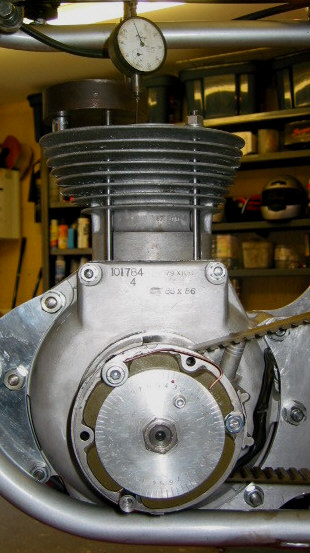
With the cylinder head off, fit one degree disc on the crankshaft as you would imagine. Arrange the dial gauge on the piston crown, preferably on a flat area like the squish band. Find TDC by reading the degree disk with the piston .200" down before and after TDC and splitting the difference. Set up the pointer accordingly.
Mark the degree disk with the specified max lift points for each cam, which for the Hot Road Cams are 103 BTDC for the exhaust cam and 101 ATDC for the inlet cam.
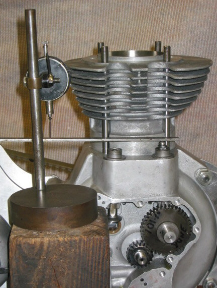
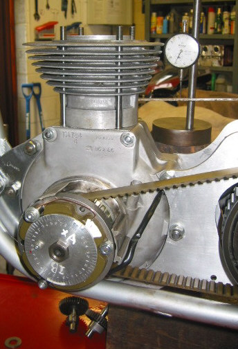
Move the dial gauge from the cylinder head and arrange it to measure cam lift. On a featherbed you can run a piece of strip metal from the upper, rear, frame cross-piece and rest it on the top of the cam followers. The dial gauge can then rest on any part of the strip, but should be arranged to be read from the drive side.
The next steps should be carried out with only one cam fitted at a time.
Set the crank rotation to the appropriate mark on the degree disk 103 BTDC for the exhaust cam and 101 ATDC for the inlet cam.
Fit the cam at what appears to be max lift. Rotate forwards and backwards and zero the dial gauge at max lift.
Rotate the crank either side of max lift, watch the dial gauge and read the degree disc to verify that you are close to correct. Zero the dial gauge at max lift.
The exact max lift point is found in a similar way to exact TDC - split the difference of similar before and after cam lifts.
Choose, for example minus 0.200", as the dial gauge reading to use before and after max lift.
The next bit is is important! To ensure that backlash in the gears does not introduce error, make the next two readings rotating the crank in a forward ie normal running, direction. Rotate the crank backwards past the point where the dial gauge reads minus 0.200". Rotate the crank forwards noting the degree disk reading at .200" before max lift and .200" after max cam lift. MARK THESE ON YOUR SPARE DEGREE DISC. Attempting to find the mid point of these two readings is not intuitive and can lead to error and pain in one's Hard Sums Cerebral Cortex. Looking at the degree disc below we can see equivalent points of lift either side of the target max lift point. These are labeled "a" and "b".
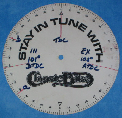
The degree disc gives values of 48 degrees ABDC and 68 degrees BTDC. If you can find the mid point by mental arithmetic - terrific! By marking up the spare degree disk it is easy to count the degrees between "a" and "b". It is 64 degrees. Max lift is therefore at 32 degrees more than "a" or 32 degrees less than "b". This turns out to be 100 degrees BTDC, which is within a degree of target.
The cam pinions have 40 teeth, so each tooth represents 9 degrees (360/40). The cam pinion is keyed onto the cam by one of 3 keyways that are arranged to give positions "between" teeth. So accuracy to within one and a half degrees is possible. If your measurement is more than 9 degrees out, engage another tooth. If between 2 and 9 degrees use another keyway. Less than 2 degrees is as good as it gets!