Fitting Instructions for Hot Road Cams
If
you feel any of this is too involved, give the job to an expert!
These
cams have been designed to give a “fast road” performance, and are
deliberately not full race profiles, with all that that means… power
loss and temperament at low to mid rev ranges.
The
standard Norton timing chest does not provide for much increase
in cam lift. Check the clearance between your existing cam at full lift
and the follower when raised to its full extent. If there is not room for
the additional 0.054” lift of these Hot Road Cams, the cam follower
block will need to be shortened. (Any cam with less lift is extremely
unlikely to give comparable performance.)
I and several other people have fitted these cams without needing to increase the cam follower movement, BUT...
Let
us assume that you do need to shorten the cam follower blocks.
Fitting and timing these cams is a job that can only be undertaken with
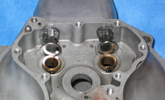
the engine out and stripped. With the timing side crankcase separated,
remove the cam bushes and the cam follower blocks. This involves drilling
out the cam block locating pin, heating the cases and unscrewing the
block. The bottom end of the cam follower block can then be ground to make
provision for the additional lift. About 1.5mm should be enough, but refer
back to your earlier measurements.
Check that the new cams rotate freely.
Timing Instructions for Hot Road Cams
Rebuild
the engine, but do not fit the head. Set up a degree wheel on the crank
and determine TDC. (The best method is with a dial gauge or vernier
calliper measuring a certain piston drop either side of TDC and splitting
the difference)
The
cams have three keyways to enable timing “between” the teeth. It is
necessary to find which keyway gives the most accurate timing. Original
cam pinions are a very tight interference fit and require a press to
remove. A local engineer will be able to help. Once off, the cam wheels
should be polished on their interior surface until they are only a firm
hand push on the shafts.
Fit
the cam wheel using any one of the keyways on the cam shaft.
Fit
the assembly into the timing chest
Set
up the dial gauge to measure cam follower movement.
| The Exhaust cam should give full lift at 103 degrees BTDC | |
| The Inlet cam should give full lift at 101 degrees ATDC |
If this is within a couple of degrees, strip and reassemble the cam and pinions on the same keyways with Loctite. Alternatively reassemble using the second and then third keyway until the best timing is obtained. Use the best keyway and Loctite in position.
Checking Valve to Piston Clearance.
Standard
pistons should not need modification, but this check is essential!
Assemble
the Cylinder head using Amal Concentric Carburettor springs in place of
the valve springs.
Fit
the head without pushrods.
Set
the piston at TDC.
Measure
the valve travel, seat to piston. Assuming standard rockers with a 1.32:1
ratio, this needs to be 0.354” times 1.32 plus 0.060 for safety. That is
0.530” travel.
Pocket the piston if necessary.
Check Valve Springs
Again, it is unlikely that any problem will be encountered, but this check is essential.
With the additional lift it is conceivable that the valve springs could become “coil bound” This is unlikely, but you must ensure that this is not so. Feeler gauges at full lift between the spring gyres) Solutions include machining the extra 0.080” or so from the ally of the cylinder head under the valve spring collar.